Here is a prototype button layout/cover just cut from a thin plastic lid like a pringles can. I used two layers, it gives you enough feel to find all the buttons. Pressing the upper layer has not caused any misfires on the other buttons. Now to make something nicer looking.

More info coming soon, I plan to put this on Instructables as well. I just need to drag my tripod out so I can take a few pictures that are not blurred.

I cannot take a good image unless I use a tripod, my natural shake is evident in most of these pictures (soldering was worse), this one below is no different. And it was the best of the many I took..oh well, you can see the copper trace exposed on SW14 near the bottom. This is where I soldered the switch leads, and since the controller uses a common ground, I soldered only one ground lead to the vibration motors terminal post. Just for the heck of it, I covered the switch pad with silicon glue to help stabilize the wires a bit.
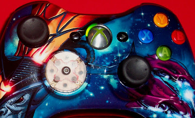
My goal is to make a new set of buttons that will make sure when I hit the upper left portion of the dpad, I actually get that action. As you are aware with the current dpad you can shave away some of the plastic to make it work better, but you still do not get the accuracy of having eight individual buttons. I will paint the lexan cover plate to match the rest of the controller as best as I can. This will at least hide the ugly pcb board from Radio Shack.
I still need to fabricate a new set of buttons that will cover this, and currently I use a small piece of carbon fiber rod to hit the switch on the bottom layer. So far it works like it should, and in short testing it was 100% accurate.
I am using 6.5mm x 6.5mm x 5mm tact switches, a total of eight. Additionally, I have eight Schottky diodes on the bottom layer board to separate the diagonal (upper level) buttons from the main buttons. All the parts used were locally purchased, and so far my budget has been under $15. In the future I could order smaller switches off the internet, but for now I just wanted to make sure everything would work.
Additional images.


